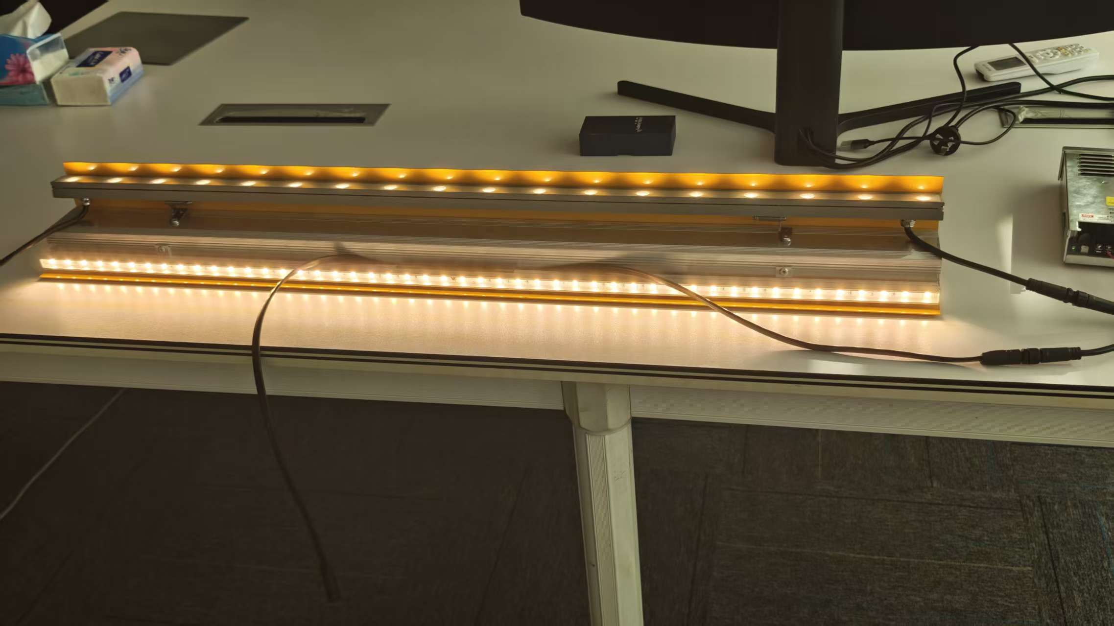
How Does an Outdoor LED Light Survive Extreme Weather? Inside Our Thermal Cycling Test Lab
Every manufacturer has an IP65 certificate. Framed. On the wall. Ask the guy who actually shows up to fix broken lights in Dubai or Oslo, though — he'll tell you something different. Water ingress almost never happens on Day 1. It happens on Day 274. After the third heatwave and the first winter freeze.
Here's what kills lights on a facade: not rain. Heat. Then cold. Then heat again. By noon, that aluminum housing is cookware — 70°C easy. By midnight, after a thunderstorm rolls through, it's ice-cold.
The metal expands. The plastic doesn't. The seal stretches. Then it shrinks. Then it cracks. And that IP65 rating you paid extra for? Useless. Now there's condensation inside the lens. Then flicker. Then dead. So we stopped trusting IP ratings alone. Every new design runs through seven separate test protocols in our lab — not one. Here's what happens in each.
Test 1: Low-Temperature Startup (What Happens at -20°C When the Grid is Weak?)
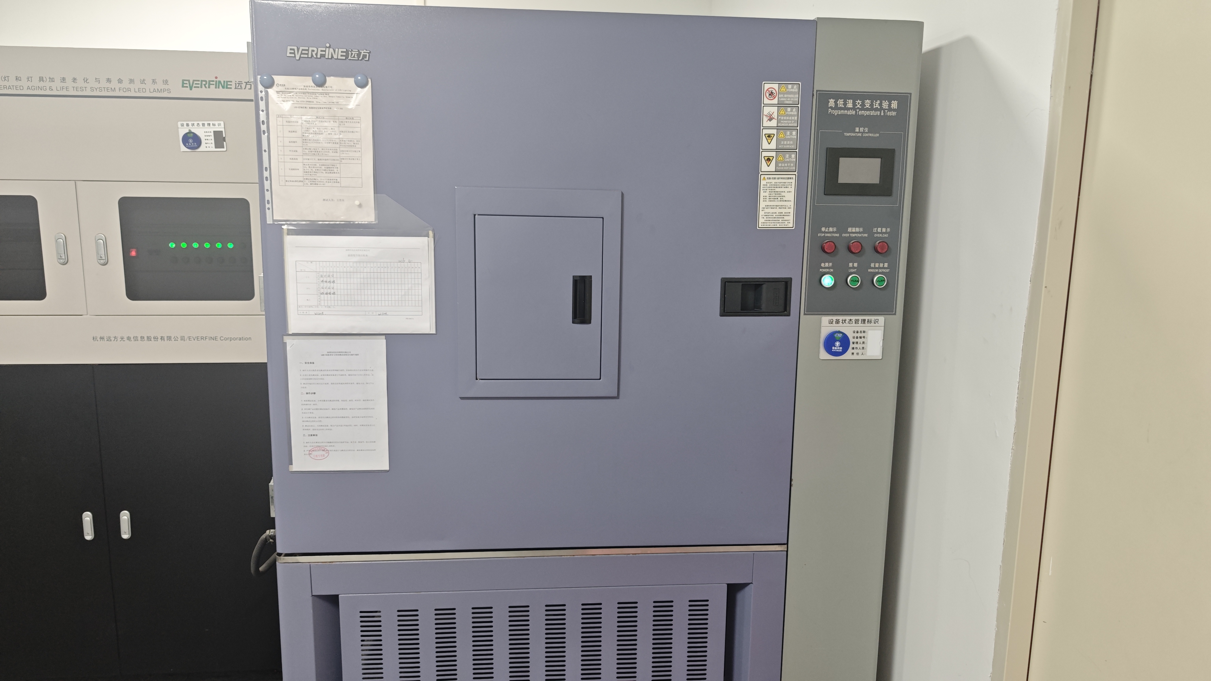
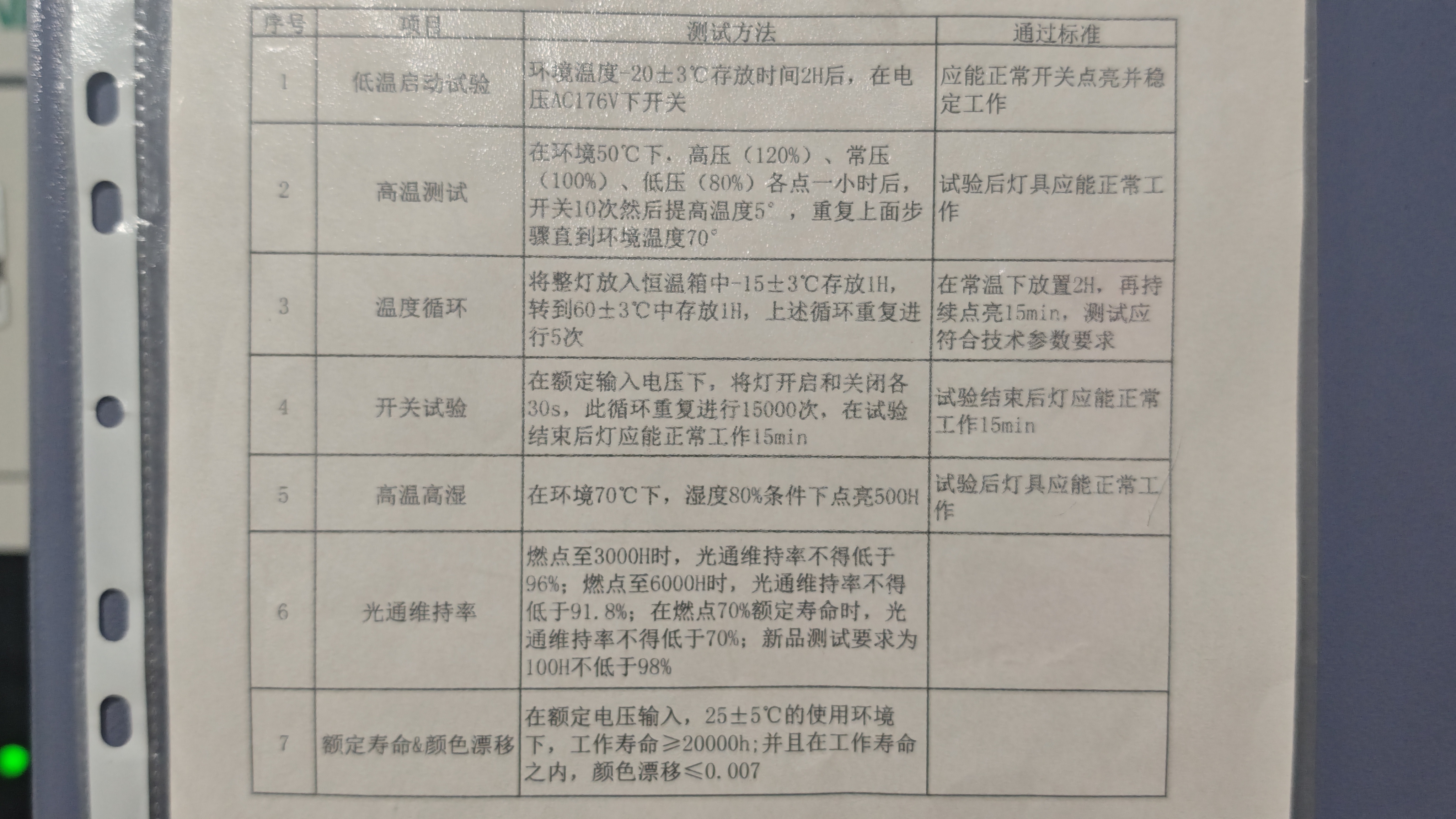
We place the fixture in a chamber at -20°C (±3°C) for 2 hours. Then we switch it on. But here's the catch — we feed it AC176V, not 220V. That's 80% of rated voltage, simulating a weak grid or a long cable run in a suburban project.
The fixture must not only start — it must stay stable. No flicker. No drop-out. If it passes, it goes to the next test. If it doesn't, back to engineering.
Why this matters to your project: grid voltage in real-world sites is rarely a perfect 220V. 176V is not a rare event. We test for it.
Test 2: Step-Up Heat Test (50°C → 70°C, One Degree at a Time)
We start at 50°C ambient. We power the fixture for 1 hour. Then we switch it on and off 10 times. Then we raise the temperature by 5°C. Wait another hour. Switch 10 times. Raise again. We repeat this until we hit 70°C — and sometimes beyond, depending on the fixture's thermal behavior.
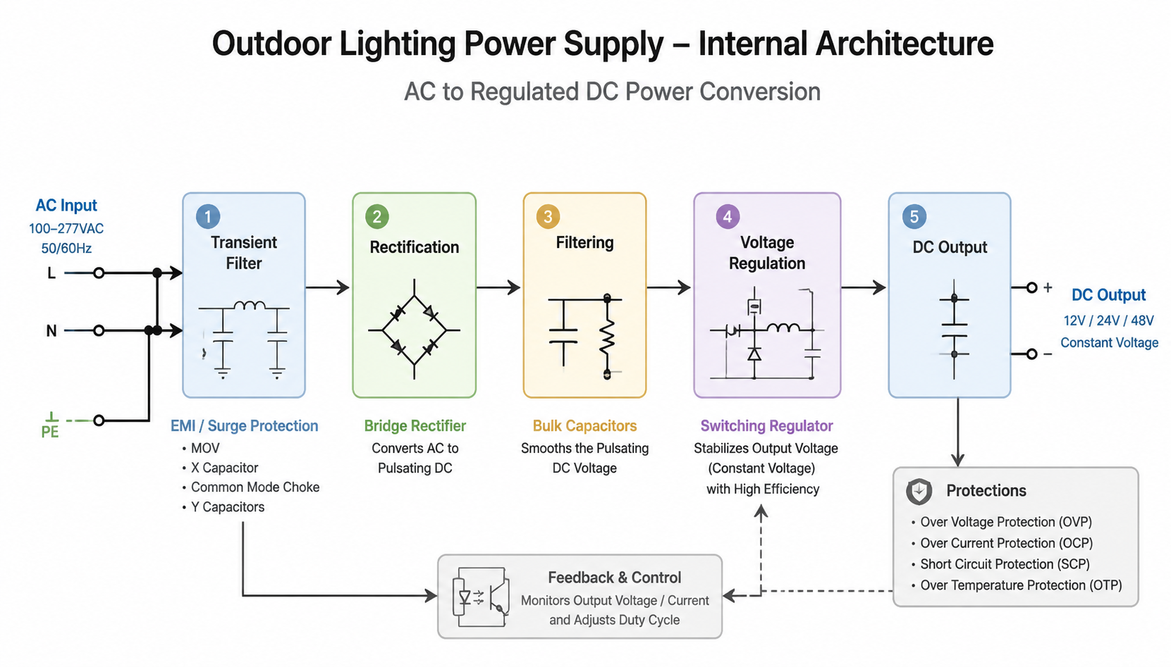
The testing focuses on monitoring the drive for thermal runaway. Some drives operate stably at 50°C but begin to oscillate at 65°C. Certain power MOSFETs experience a drop in efficiency as the temperature rises, leading to increased current and further heat generation; this creates a vicious cycle that can ultimately result in catastrophic failure.
We catch that in this step-up test, not in a static 70°C soak.
Test 3: Thermal Cycling (-15°C ↔ +60°C, 5 Cycles)
The chamber does this:
-15°C (±3°C) for 1 hour——Room temperature for 2 hours (this is the "transition" phase — the fixture experiences the most stress during this swing)——+60°C (±3°C) for 1 hour——Repeat 5 times
This is a direct simulation of a night-to-day-to-night cycle. The air temperature swings from -15°C to +60°C — but the aluminum housing surface? On a sunny day, that surface can hit +70°C to +80°C due to solar gain. So while the chamber air says 60°C, the fixture itself is experiencing closer to 80°C at the hottest moment.
We watch for:
Seal compression set (does the gasket still seal after 5 expansions and contractions?
Solder joint micro-cracks (thermal expansion mismatch between PCB copper traces and ceramic LED packages)
Lens detachment (optical silicone loses adhesion after repeated stress)
5 cycles is our baseline. We've run some designs up to 20 cycles. If a fixture fails at Cycle 6, it doesn't ship.
Test 4: On-Off Endurance (15,000 Cycles — 30 Seconds Each)
This test runs in the background while others are running.
We switch the fixture ON for 30 seconds, OFF for 30 seconds. Repeat 15,000 times.
The figure of 15,000 cycles was selected to simulate a typical commercial lighting system operating for approximately 12 hours a day. If the control system switches the lights on at dusk and off at dawn, this results in roughly 730 switching cycles per year; thus, 15,000 cycles—equivalent to about 20 years of daily operation—are condensed into this single test.
We do this at room temperature and also at -20°C (because relays and electrolytic capacitors behave very differently in cold).
Passing this test means you won't get a call from the client at Year 3 saying "half the building just went dark."
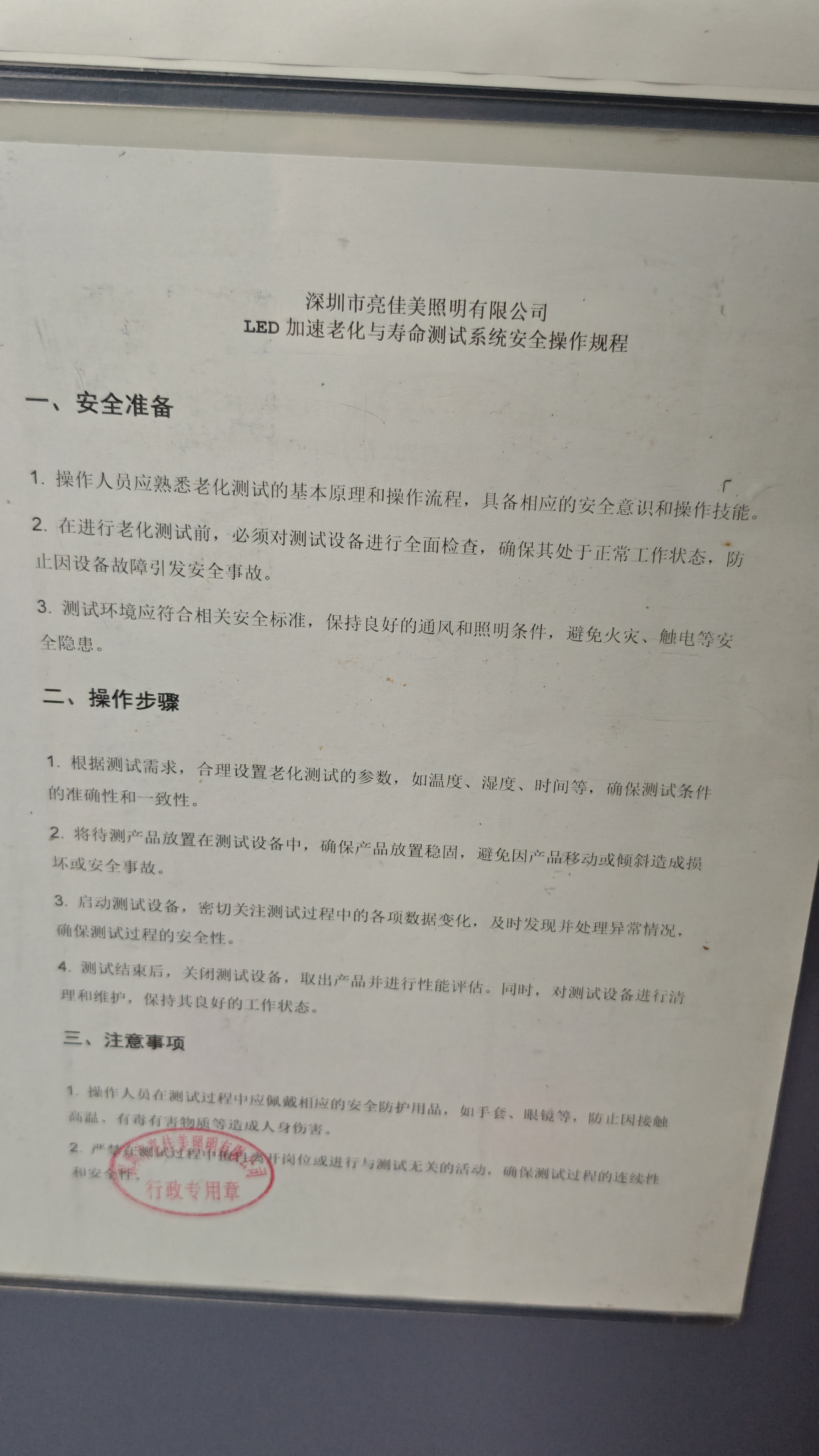
Test 5: Damp Heat (70°C, 80% Humidity, 500 Hours)
This is the "Southeast Asia / coastal Florida" test. We run the fixture at 70°C ambient with 80% relative humidity for 500 continuous hours. 70°C is the upper limit of what a facade fixture experiences in direct sunlight in tropical climates. 80% humidity is the threshold where moisture can penetrate through tiny capillary gaps that dry air cannot.
What fails in this test?
PCB corrosion (copper traces disappear under the solder mask)
LED package yellowing (the phosphor layer absorbs moisture and degrades)
Driver transformer insulation breakdown (moisture + high voltage = leakage current)
We've seen fixtures from other brands fail this test before the 200-hour mark. Ours run the full 500. Then we cut them open and inspect every component.
Test 6: Lumen Maintenance (3000H at ≥96%, 6000H at ≥91.8%)
We burn the fixture continuously and measure light output at intervals. Our minimum requirements:
|
Time |
Minimum Lumen Maintenance |
|
3000 hours |
≥96% |
|
6000 hours |
≥91.8% |
|
70% of rated life |
≥70% |
|
New unit (100H) |
≥98% |
To put that in perspective:
3000H is about 1 year of 8-hour nightly operation; 6000H is about 2 years. 70% of rated life for a 50,000H-rated fixture is 35,000H — about 12 years of nightly operation.
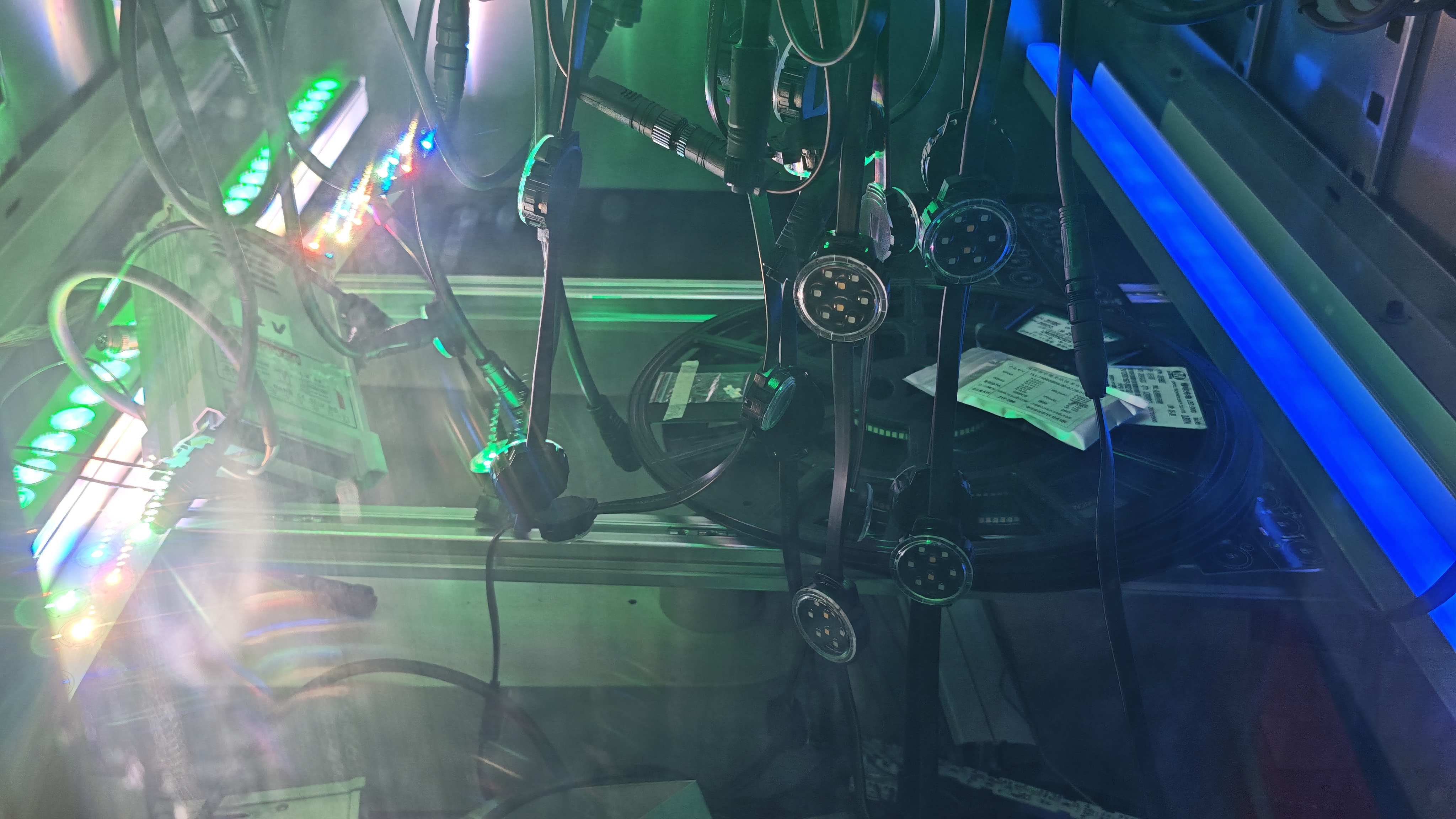
Test 7: Color Shift (Δuv ≤ 0.007 over 20,000 Hours)
This is the one most specifiers forget — until they see a building facade where the new and old fixtures look like two different colors next to each other.
We measure chromaticity shift (Δuv) over the lifetime of the fixture. Our spec: Δuv ≤ 0.007 over 20,000 hours. For reference, the human eye can detect a color shift of approximately Δuv = 0.005 to 0.008. At ≤0.007, we're keeping the color perception stable through the useful life of the installation — meaning the wall you see at Year 0 looks the same as Year 5.
We achieve this through:
Carefully binned LED packages (not mixing bins across a project)
Thermal management that keeps junction temperature stable (temperature variation is the primary driver of color shift in phosphor-converted white LEDs)
Our thermal cycling test ensures the die-attach material doesn't degrade, which would change the thermal path and shift the color temperature
Conclusion
The seven tests above run on every new fixture design before it goes into production. Your project site won't be tougher than our lab. That's the point.
If you want to see the actual test reports for a specific fixture — thermal cycling logs, lumen maintenance curves, color shift data — we'll send them.
Because "IP65" tells you it repels water. Our test protocols tell you how it survives.
FAQs
Q1: Why is IP65 not enough for outdoor LED lighting?
IP65 only proves that an LED fixture can resist dust and water ingress under controlled testing conditions. It does not show how the fixture performs after years of temperature changes, material expansion, contraction, and weather exposure. In real outdoor projects, many failures happen because repeated thermal cycling damages seals, adhesives, solder joints, and internal components over time.
Q2: What is thermal cycling testing for outdoor LED lights?
Thermal cycling testing simulates repeated temperature changes that outdoor LED fixtures experience in real environments. The fixture is exposed to extreme cold and heat cycles to check whether materials, seals, solder joints, lenses, and electronic components can withstand thermal expansion and contraction without failure.
Q3: What temperature range should outdoor LED lights be tested for?
A reliable outdoor LED fixture should be tested across a wide temperature range based on its application environment. Many professional tests include low temperatures around -20°C to -40°C and high temperatures from +60°C to +80°C to simulate extreme climates such as northern Europe, deserts, and tropical regions.
Q4: Why do LED lights fail after several months instead of immediately?
Most outdoor LED failures are caused by long-term stress rather than initial installation problems. Repeated heating and cooling cycles create mechanical stress between different materials such as aluminum housings, PC lenses, silicone seals, and PCB components. Over time, small cracks, seal failures, condensation, and electronic damage can develop.
Q5: How does temperature affect LED driver performance?
High temperatures can reduce LED driver efficiency, increase component stress, and shorten the lifespan of critical electronic parts such as capacitors and MOSFETs. Low temperatures can also affect startup performance and voltage stability. Thermal testing helps identify driver problems before products are installed on real projects.