SMD vs COB LED Comparison: In-Depth Technical Guide and Buying Advice
SMD (Surface-Mount Device) and COB (Chip-On-Board) represent two mainstream LED packaging strategies used across architectural, commercial and entertainment lighting. SMD emphasizes modularity and color flexibility—ideal for linear fixtures, LED strips and pixel-controlled displays—while COB offers dense, uniform light output and superior single-unit lumen capacity, making it a frequent choice for high-quality downlights, floodlights and display lighting. There is no universal “better” option; the right choice depends on visual goals, available thermal area, budget and maintenance strategy. This article presents a structured, engineer-friendly comparison and practical project guidance you can use for specifications, procurement and on-site acceptance.
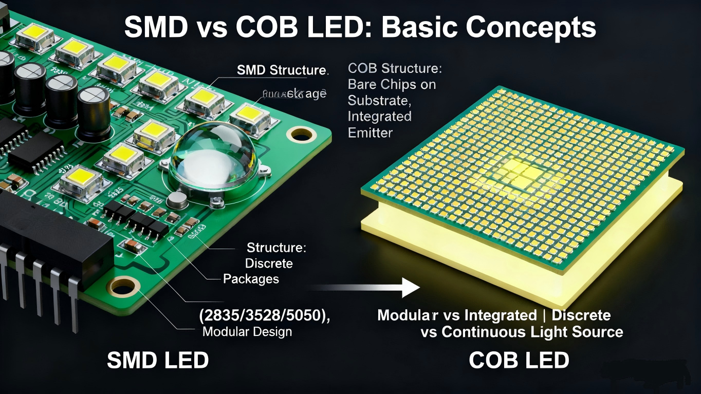
1. Basic Concepts
SMD LEDs are pre-packaged LED chips mounted on PCBs or flexible circuits. Typical package codes (e.g., 2835, 3528, 5050) indicate size and internal chip arrangement. Because each package is a discrete, testable unit, SMD arrays are extremely modular and lend themselves to pixel control, multiple color mixing, and large-area coverage with straightforward mass production and replacement. Optical design (lens, diffuser) and layout are the keys to shaping SMD output.
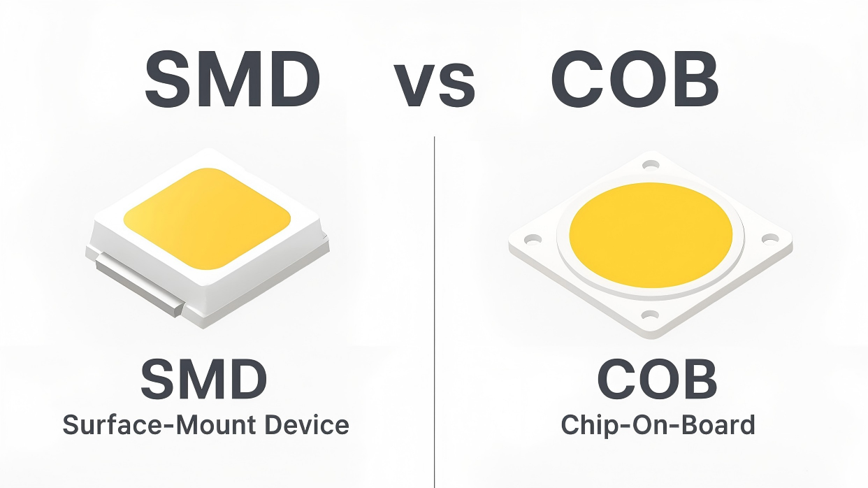
COB places bare LED chips directly onto a single substrate, producing a continuous, high-density emitting surface. Removing multiple intermediate package layers shortens thermal paths and allows higher luminous flux per unit area. The visual result is a smoother emission (less visible “point” structure), which favors applications requiring uniform illumination and high color fidelity. COB demands careful thermal integration and robust mechanical design to realize its advantages.
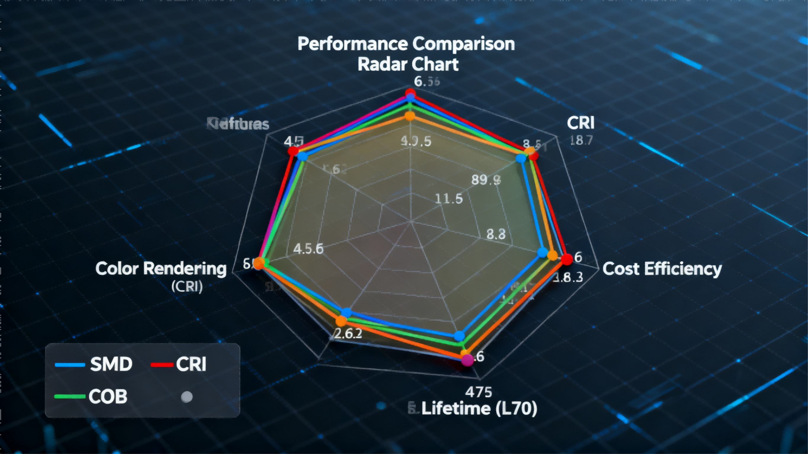
2. Key Performance — Deep Comparison
2.1) Luminous Efficacy (lm/W)
SMD technology achieves consistent luminous efficacy at low-to-moderate power levels thanks to mature packaging and sorting processes; therefore SMD is efficient and predictable for linear fixtures and backlighting scenarios. When very high luminous flux per unit area is required, however, densely packed SMDs increase local thermal load and practical lm/W may drop unless advanced cooling is provided.
COB excels when designers need high lumen output from a compact light source. Because chips share a short thermal path to the substrate, properly cooled COB modules often deliver superior system-level lm/W in mid-to-high power fixtures like floods, stage wash lighting and compact downlights. That benefit is conditional: the lamp or luminaire must have adequate heat-sinking. System-level measurements (installed lm/W at rated current and operating temperature) are the correct comparison metric — not just datasheet chip numbers.
2.2) Color Rendering (CRI) and Color Stability
SMD offers great flexibility: multi-chip packages or hybrid arrays enable tunable white and dynamic RGB(W) color mixing. This makes SMD the natural choice where color effects, pixel control or variable correlated color temperature (CCT) are priorities. However, multi-source mixing requires well-designed optics and spacing; insufficient mixing can produce visible color spots or non-uniformity at short viewing distances.
COB’s continuous emitting surface tends to deliver more consistent perceived color and is typically easier to achieve high CRI values (e.g., CRI ≥ 90) with fewer mixing artifacts. For applications where accurate color reproduction matters—museum lighting, retail product highlights, artwork illumination—COB lamps commonly provide a more natural, uniform color appearance under similar conditions.
2.3) Thermal Management
SMD assemblies are inherently “point-source” thermal systems: each package dumps heat into the PCB and then into the fixture. PCB copper thickness, thermal vias and overall thermal path design determine how well the heat is conducted away. High-density SMD layouts increase thermal design complexity and may require larger heatsinks or forced convection for long-term reliability.
COB’s direct chip-to-substrate contact shortens the thermal path and spreads heat more evenly across the baseplate, often enabling lower junction temperatures under equivalent output. That said, COB requires very good mechanical contact with the heatsink, high-quality thermal interface materials, and controlled assembly processes. Any gap, contamination or degraded thermal compound will quickly reduce performance.
2.4) Beam Control and Visual Appearance
SMD’s discrete elements allow designers to tailor beam patterns with a wide variety of optics: micro-lenses, reflectors and diffusers can create narrow spot, wide flood, linear wash or highly pixelated effects. This optical freedom makes SMD ideal for strip lighting, signage and applications where shaping the image or pattern is central.
COB produces a soft, unified beam with reduced “sparkle” or point-like structure. For applications that prioritize comfortable, even illumination—downlights, gallery accent lights, hospitality spaces—COB typically provides a pleasing, low-artifact light field. While COB can be paired with secondary optics for beam control, it is less convenient for producing high-resolution pixel effects.
2.5) Lifetime and Lumen Maintenance
Lifetime is commonly reported as L70 or L80 (hours until lumen output falls to 70%/80% of initial). Both SMD and COB can achieve long lifetimes (50,000+ hours) under correct thermal and current conditions. The key drivers of lumen depreciation are junction temperature, drive current and environmental stress. SMD assemblies with poor local cooling may show accelerated lumen depreciation at the package level; well-designed COB fixtures generally maintain lumen output better at high flux densities because of superior heat spreading. Always request vendor-provided system-level LM (lumen maintenance) test data performed on the actual assembled luminaire, not just the bare LED.
2.6) Cost and Manufacturing Flexibility
SMD parts benefit from established supply chains and automated surface-mount assembly processes, which keep per-unit cost low and enable flexible product variants (color options, pixel mapping). COB can deliver a better lumen-per-cost ratio at higher outputs because fewer discrete packages and solder joints are needed, but it often requires more engineering effort on heatsink design and assembly tooling. For high-volume decorative or display products, SMD’s modularity is a major advantage; for performance-focused fixtures where high-power single-source output matters, COB may be more cost-effective at scale.
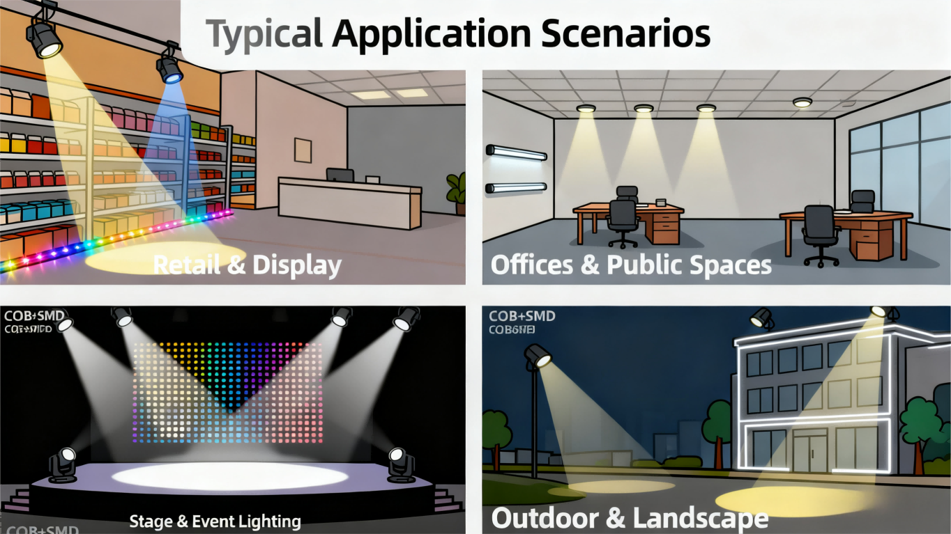
3. Typical Applications — Demand-Based Subsections
3.1) Retail & Display — Balancing Attraction and Color Fidelity
Retail lighting must both attract attention and render merchandise faithfully. SMD’s capacity for pixel-level control enables animated accents, outline lighting and interactive displays that capture foot traffic. COB, conversely, shines where accurate color and soft, shadow-free illumination are essential—think product highlights, jewelry case lighting or apparel displays. A hybrid approach is common: COB downlights deliver natural color to products, while SMD strips create dynamic visual interest along edges and architectural features.
3.2) Offices & Public Spaces — Comfort versus Flexibility
In office and public environments, consistent glare control and visual comfort are priorities. COB downlights and troffers produce smooth, comfortable illumination with minimal point-source glare, making them suitable for meeting rooms and general illumination. SMD linear fixtures provide modularity for task-based layouts and future reconfiguration. Combining COB for baseline ambient light and SMD for zonal or accent lighting yields a balance between comfort, flexibility and maintainability.
3.3) Outdoor & Landscape Lighting — Range, Durability and Optics
Exterior projects demand distance, weatherproofing and robust optics. COB is frequently selected for long-throw floodlights and architectural washes because a single high-lumen COB reduces fixture count and delivers stable color at distance. SMD is often used for façade lines, contour lighting or pixel-mapped façades where linear arrangements or dynamic content are required. Designers must weigh installation height, desired viewing distance and local maintenance capabilities when choosing a hybrid or single-technology approach.
3.4) Stage & Event Lighting — High Output and Dynamic Backgrounds
Live events require both high-intensity key light and flexible background/atmospheric effects. COB fixtures serve as reliable key or fill sources with high CRI and stable output, while SMD-based panels and strips provide colorful, animated backdrops and pixel effects. Because event rigs change rapidly, SMD’s serviceability and modular replacement can reduce downtime, while COB maintains consistent on-stage color rendition.
3.5) Case Studies & Hybrid Strategies — Practical Lessons
Successful projects often partition responsibilities: use COB to deliver primary, high-quality illumination and SMD to supply decorative or interactive layers. For instance, high-end retail stores often deploy COB downlights for product fidelity and SMD accent strips for brand animation—this keeps procurement costs manageable while preserving visual quality and serviceability.
4. Project-Level Selection & Design Recommendations
4.1) Convert Visual Goals into Measurable KPIs
Translate qualitative aims into quantitative KPIs: target average lux, peak/local lux, minimum CRI, maximum SDCM, permitted UGR (glare) and color uniformity across zones. These KPIs inform whether COB or SMD (or both) should be used in each lighting layer.
4.2) Site Survey and Thermal Budgeting
Evaluate available thermal area, expected ambient temperature range, ventilation and mechanical constraints. Build a thermal budget: determine acceptable junction temperatures and back-calc allowable drive current. For COB, ensure substrate-to-heatsink thermal resistance is calculated and within the device’s allowed margin; for dense SMD arrays, verify PCB copper weight, via placement and heat spreading capability.
4.3) Specification Document & Vendor Data Requirements
Require vendors to submit system-level test data for sample luminaires: installed lumens, system lm/W, IES files, measured CCT and SDCM, θJA/θJC tests and accelerated aging results. Put lamp-level acceptance criteria into the contract, including rework and warranty terms tied to measured performance, not only to datasheet numbers.
4.4) Optical, Electrical and Control Integration
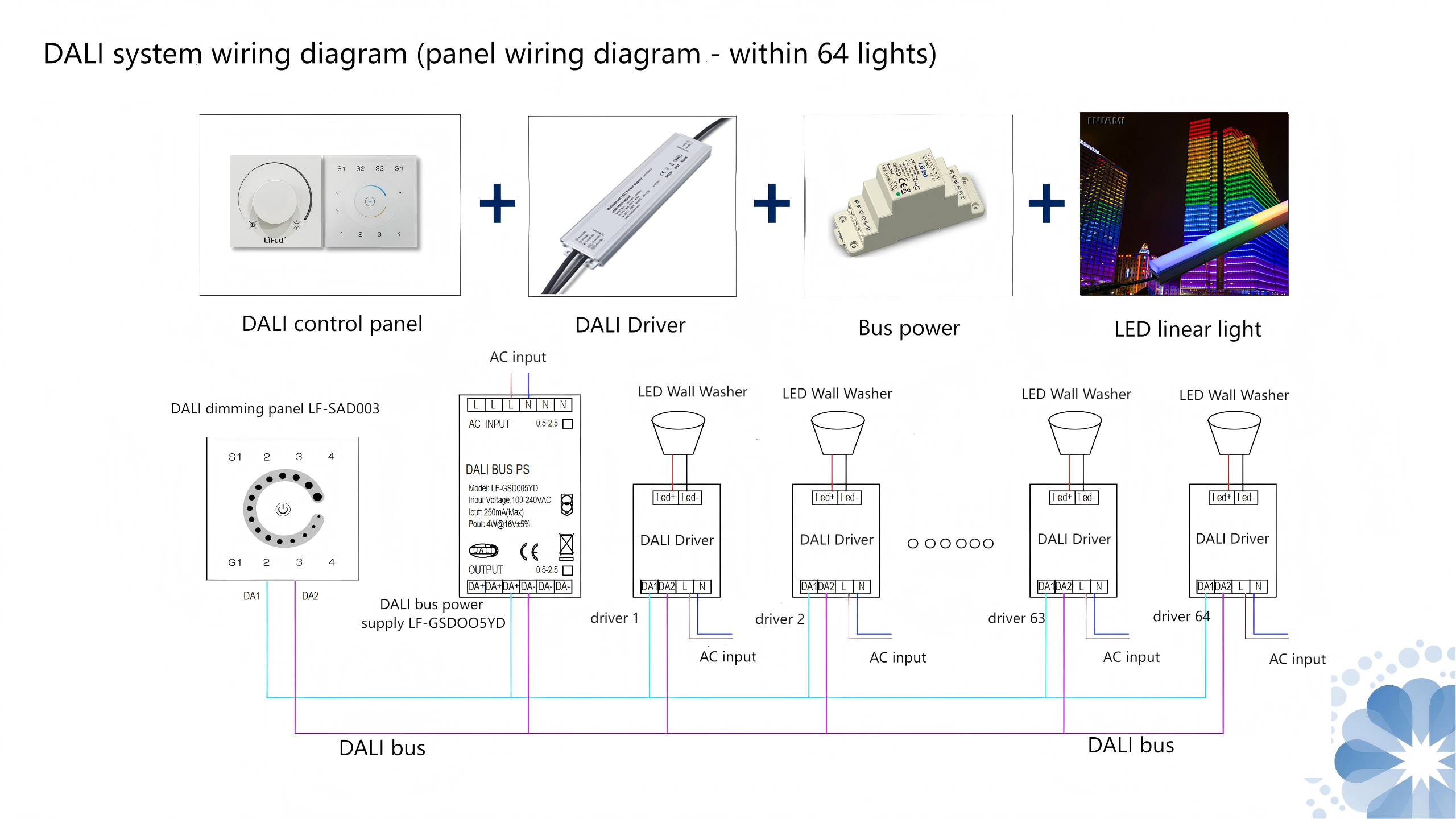
Obtain full photometric data (IES files) and simulate in the intended space. Ensure driver selection meets power factor and THD requirements, supports the chosen dimming protocol (DALI, 0-10V, PWM, etc.), and addresses flicker/temporal modulation concerns. Resolve addressing, grouping and control wiring early to avoid on-site integration issues.
4.5) Procurement, Sample Testing and Acceptance Process
Follow a staged procurement: order samples → perform system-level tests (lumens, color, thermal) in the fixture housing → run a pilot installation → proceed to volume purchase only when acceptance tests meet KPI thresholds. Acceptance should require fixture-level (installed) verification, not just component verification.
5. Installation & Maintenance (Practical Procedures and Standards)
5.1) Pre-Installation Checks and Preparation
Perform a thorough incoming inspection: verify batch numbers, confirm no shipping damage, and check that all thermal interface materials, fasteners and seals are included. Coordinate with MEP teams to confirm power capacity, protective devices and earthing are in place before powering luminaires.
5.2) Mechanical Mounting and Thermal Interface Best Practices
For COB fixtures, ensure the heat-spreader surface is clean, flat and mated with the heatsink using the manufacturer-recommended thermal pad or compound and correct compression. For SMD modules, avoid mechanical stress on PCBs; use compliant fasteners and strain relief for connectors. For exterior installations, treat metal parts to resist corrosion and allow for thermal expansion without compromising thermal contact or seals.
5.3) Electrical Wiring, Protection and Commissioning Steps
Install protective devices—overcurrent, overtemperature and earth leakage protection—close to the distribution board. Commission in phases: validate driver output under no-load, then apply load to measure current, Vf and junction temperature rise. Test dimming ranges and verify there is no flicker or communication dropouts across the control system.
5.4) Maintenance Schedule, Logs and Traceability
Define a maintenance plan: monthly visual inspection and cleaning, quarterly driver and color drift logs, and annual lumen maintenance measurements. Track replacements with batch/lot numbers and hours-run to trace any production defects or premature depreciation. Keep a small on-site spare pool for critical fixtures.
5.5) Troubleshooting Workflow and Spare Parts Policy
Troubleshoot in order: driver stability → junction temperature → optics contamination or displacement → mechanical/thermal interface failure. Maintain 5–10% spare modules for critical assets (adjust percentage based on site criticality) and ensure spares match the production batch to prevent visible color shifts.
6. Environmental, Efficiency & Compliance Considerations
6.1) Certifications and Regulatory Baseline
Prefer components and fixtures certified to IEC/EN/UL standards and request RoHS/REACH/EMC documentation. For export projects, confirm the target market’s regulatory requirements (e.g., UL for North America, CE for EU) and include certification checks in acceptance testing to prevent costly rework.
6.2) System Efficiency and Smart Controls
System-level efficiency (installed lm/W) is what drives operating cost. Integrate occupancy sensing, daylight harvesting and scheduled dimming where appropriate. Early-stage energy modeling for large projects helps quantify the OPEX savings from more efficient arrays and smarter controls.
6.3) Light Pollution, Blue Light and Human-Centric Principles
Control upward spill light in urban projects to reduce skyglow and impact on wildlife. Minimize short-wavelength blue peaks for exterior and night-time installations and use spectral tuning or warmer CCTs where circadian impact is a concern. For interiors, apply human-centric lighting strategies—adjustable CCT and intensity—to improve occupant comfort and performance.
6.4) Material Recyclability and End-of-Life Management
Favor heat sinks and structural components made from high-recyclability metals and mark plastic parts for recyclability. Contractually define end-of-life take-back, recycling or refurbishment options with the vendor to reduce disposal costs and environmental footprint.
6.5) Life-Cycle Costing (LCC) and Payback Analysis
Evaluate options using life-cycle costing: upfront CAPEX, predicted energy use, scheduled maintenance, and replacement intervals. High-efficiency, longer-life fixtures often repay the premium through reduced energy and maintenance costs—quantify this in a multi-year payback model to justify decisions to stakeholders.
Conclusion (Practical Guidance)
SMD and COB are not mutually exclusive choices; they are complementary tools. Use COB where high-quality, uniform illumination and high lumen density are required; use SMD where flexibility, pixel control and modularity are priorities. The best projects set clear KPIs, require system-level test data, allocate thermal budget and integrate optical and control systems early in design. Where necessary, deploy a hybrid approach—COB for primary illumination, SMD for decorative and interactive layers—to balance performance, cost and serviceability.
Call to action (CTA): Want a tailored specification or sample test plan for your space? Send your project details (for example: gallery 10 m × 12 m, target 3000 K, CRI ≥ 90) and I’ll prepare a practical mixed-technology LED selection, thermal plan and acceptance checklist.